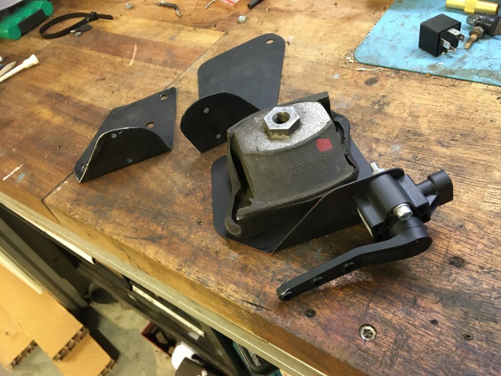
The original air suspension front axle height control valves position and location was chosen as the location of the new height sensors: mounting brackets under the engine suspension rubbers. There was no need for additional holes, and the sensor rod lower joint can be fixed in its original position.
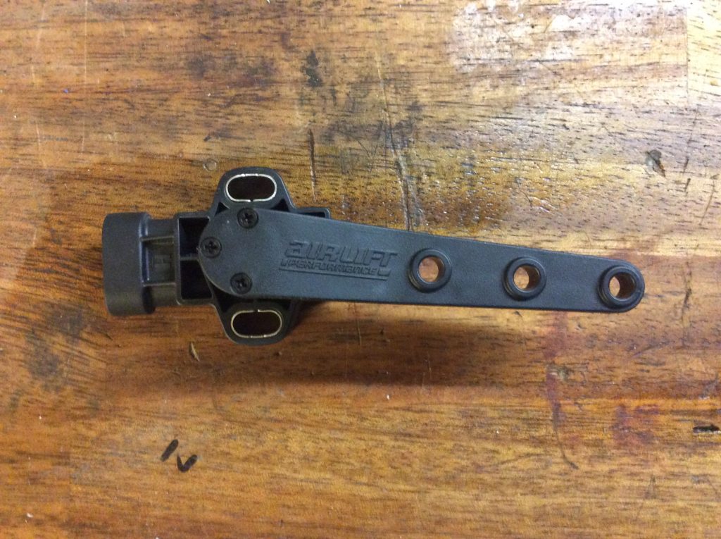
The sensor has a lot of adjustment possibilities , so the final position of the sensor can be fine tuned when the system is running.
The kit also came with a mounting template that made drilling holes easy.
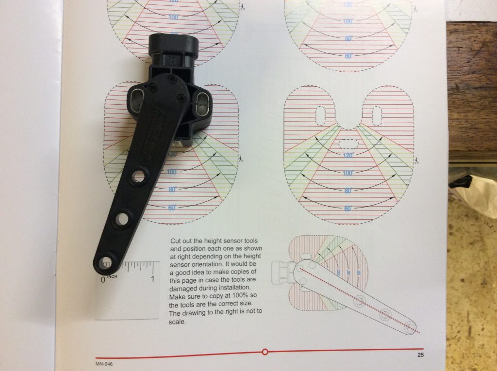
I scanned the page from assembly manual and the printed template.
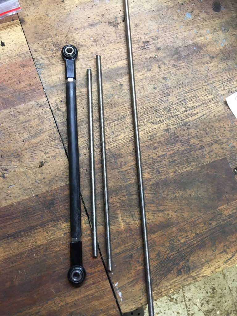
The adjusting rod included in the kit was disappointingly a couple of centimeters short, but I found from local hardware shop the M5 stainless rod at a great price. The protective rubber tube provided in the kit was also left unused as it was too short.
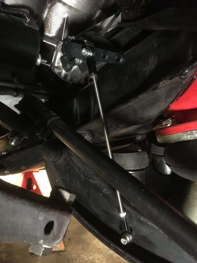
Squeezing the sensor with bracket underneath the engine mount was a small nightmare, but the result looks pretty nice. The final adjustment of the rod and sensor will not take place until the entire system is assembled.
It is a bit pity that both ball joints have same threads, now you will always have to remove the joint for adjustment. An adjustable rod with both joints with different direction threads would have been easier to adjust by simply rotating the rod.
The next step is then to install the rear sensors in section 3. (Coming soon)
Link to Part 4. http://saarelagarage.fi/wp/?p=295&lang=en
Back to part 1. http://saarelagarage.fi/wp/?p=155&lang=en